
|
'On Tunnelling by Machinery' |
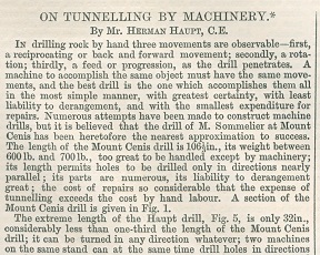
IN drilling rock by hand three movements are observable-first, a reciprocating or back and forward movement; secondly, a rotation; thirdly, a feed or progression, as the drill penetrates. A machine to accomplish the same object must have the same movements, and the best drill is the one which accomplishes them all in the most simple manner, with greatest certainty, with least liability to derangement, and with the smallest expenditure for repairs. Numerous attempts have been made to construct machine drills, but it is believed that the drill of M. Sommelier at Mount Cenis has been heretofore the nearest approximation to success. The length of the Mount Cenis drill is 106 1/3 in., its weight between 600 lb. and 700 lb., too great to be handled except by machinery; its length permits holes to be drilled only in directions nearly parallel; its parts are numerous, its liability to derangement great; the cost of repairs so considerable that the expense of tunnelling exceeds the cost by hand labour. A section of the Mount Cenis drill is given in Fig. 1.
The extreme length of the Haupt drill, Fig. 5, is only 32in., considerably less than one-third the length of the Mount Cenis drill; it can be turned in any direction whatever; two machines on the same stand can at the same time drill holes in directions nearly at right angles to each other. It weighs about 125 lb., and one man can lift it, handle it, or walk away with it. Its parts are so few and simple that it seems certain that no improvement can ever be made to reduce the number of parts even to the extent of a single piece, and yet it contains all that are required for the movements. It is not liable to derangement. The wearing parts are inexpensive and easily renewed; every part is accessible for oiling. Anyone drill can be removed and another inserted without stopping any other machine. The drilling tools are inserted at the back and not at the forward end; a minute is sufficient time to take out one and insert another. The cost of tunnelling is expected to be so much less than the cost by hand labour that a company has recently been organised in the United States to take contracts for tunnelling at the cost of hand labour, who expect to make very large dividends from the profits. The outlay for machinery and power on this system, with the direct application of steam, is not one-tenth of the expenditure required on the Mount Cenis or Hoosac plans.
|
Herman's article in The Engineer |
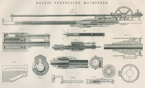 |
| Haupt tunnel drilling equipment, Figures 1-9 |
Valve.--For ordinary crank engines the slide valve is well adapted, but for drilling engines the ordinary form is seriously objectionable. Whatever may be the mode of connection between the piston rod and valve the opening into the cylinder must be by a gradual sliding movement, which opens the port for the admission of air or steam into the forward end of the cylinder before the stroke is fully completed and the blow given upon the rock. It is obvious, therefore that the steam or air is entering and retarding the velocity of the piston at the very point where it should be greatest. To overcome the difficulty the author designed and patented a balanced spring valve, the operation of which will be explained.
 |
| Haupt tunnel drilling equipment, Figures 10-18 |
The arm which moved the valve was not connected with the piston rod but was operated by springs; each movement of the piston in either direction would set one spring, and upon reaching the end of the cylinder would touch a trigger and release the spring at the opposite end, shifting the valve by an instantaneous movement, but not until the stroke had been completed. The present valve is more simple, and operates in a similar manner, the chief object being to allow the piston to complete its stroke before the valve is shifted. The form of valve now used is shown in Fig. 2. It is nothing more than a piece of pipe on which four rings are shrunk and accurately turned to fit the cylindrical steam chest in which it moves; the two middle rings open and close the ports precisely as in a slide valve when its position is shifted. If this valve had a rigid connection with the piston rod it would be a balanced slide valve moving with very little friction, but possessing no other advantage; but the rod which moves the valve is not rigidly attached to it; it terminates in a piston in the middle of the tube, on each side of which are spiral springs, held and compressed by rings screwed into the ends of the tube. 'When the stops on the valve rod are struck by the arm on the piston rod the effect is not immediately transmitted to the valve, but the spring yields to a certain extent to the blow before the inertia and friction of the valve are overcome. This gives the piston power to travel some distance after the stop is struck before its motion is retarded by the admission of steam. The perfection of a valve for a drilling engine would be one which would fulfill the following conditions: 1. A balanced valve requiring but little power to effect its movement. 2. A valve that will always be in such position as to leave one of the steam ports open so that the engine will start without difficulty, delay, or moving the valve by hand whenever steam is admitted. 3. A valve which will not open to admit steam at the end of the forward stroke so early as to retard the force of the blow, but when the blow is given will shift instantly to admit steam for the back stroke. All these conditions are fully complied with in a form of valve recently designed by the author. It is represented in Fig. 9, and consists of the following parts: A tube or rod, 1, 2, sliding within a cylindrical steam chest, and surrounded by rings which fit tightly, and form the rubbing surfaces of the valve. A valve rod passing through a gland at the forward end of the steam chest, and connected with the valve either in a rigid manner or by the interposition of springs to relieve the blow upon the end of the steam chest. A stop on the valve rod so adjusted that when the arm or the piston rod is at the end of the back stroke, it will place the valve in proper position, with the spiral spring, 4, around the valve rod compressed, and the valve fastened by the trigger, 5, which is pressed down by the spring, 6. The trigger, 5, has upon it two adjustable stops, which can be placed in such position as to shift the valve at the proper part of the stroke. When the arm, 2, commences to move forward, it has no effect upon the valve rod, which remains fastened by the first stop, but when the arm, 2, reaches the second stop, 7, the trigger is raised, the spring relieved, and the valve rod instantly projected forward by the recoil of the spring. As the stop 7, is adjustable, the length of stroke may be regulated at pleasure, but the expenditure of steam will not be reduced by shortening stroke, unless a portion of the spaces at the ends of the cylinder be filled with solid material, or the piston lengthened.
|
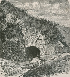
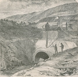
Construction of Hoosac Tunnel's eastern entrance |
The Feed Movement.--The principle of the momentum feed may be illustrated in a familiar manner. If a person should be driving rapidly in a vehicle which should be suddenly checked by coming in contact with an obstruction, he would be thrown forward with violence. So also if a drilling tool should be held in such a manner that the tool bolder could be suddenly checked, while the tool itself could move forward, a progressive movement would be the result each time that the check was given. Such a check to the momentum of the tool holder would of course diminish to some extent the force of the blow upon the rock, but if this check should only be given at intervals the loss of effect would not be serious, and even at such times the blow would be heavy from the momentum of the drill-rod 'itself, the velocity of which is but slightly retarded. The mechanism for effecting this movement is represented in Fig. 4, the parts of which will now be described and the mutual action explained: l. Represents the stud which moves in a spiral slot in the case 7, to rotate the drill. 2. A ratchet on the gripper-box to prevent rotation in the wrong direction. 3. A steel guide and pawl pressed against the ratchet 2 by a spring to bold it in position during the forward movement. 4. Box bolted or rivetted on 7 to contain 3. 5. Ratchet cut in gripper-box to effect rotation. 6. Ring which carries pawl, and which is moved by the stud 1, to effect rotation. 7. Cylindrical case bolted on end of steam cylinder which protects the working parts and carries the guides for the ratchets. 8, 8. Line of rear end of steam cylinder. 9, 9. Anvil or stops which, coming in contact with projections 18, and face of gripper box 11, detaches the drill-rod and gives a feed. 10. India-rubber ring interposed between the anvil and the end of the cylinder to relieve the concussion. 11. Gripper-box containing the wedge-shaped pieces or grippers, 15, which hold the drillrod 17. 12. Collar on end of piston-rod. 13. Volute spring interposed between the collar 12 and the grippers 15. When the motion of the gripper-box is checked by coming in contact with the stops 18 the drill-rod 17 moves forward, the spring is compressed, and the grippers are pushed backwards over the rod, taking hold at another point back of the first, and thus giving a forward feed. 14. Washer which is bevelled to prevent the grippers from falling out when the drill-rod is removed. 15. Grippers to hold drill-rod, the surfaces of which, as also of the drill-rod, may either be smooth or ridged. If smooth the surfaces must be free from grease or the adhesion will not be sufficient to prevent the drill-rod from slipping backwards and thus losing the feed. 16. Follower, which, by being screwed into the back end of the gripper-box, compresses the spring 13, releases the grippers 15, and permits the drilling tool and holder 17 to be readily withdrawn from the rear end without interfering with the work of any other machine. 17. Drill holder. 18. Projections of about one-third of an inch on the gripper-box, which, coming in contact with the anvil or stop once or twice in a rotation, produces the feed. The three diagrams A, B, and C all refer to Fig. 4, and the corresponding parts have the same numbers. It will be perceived from this description of parts that the feed is given by the projections on the gripper-box coming in contact with the stops on the cylinder head; this causes the drilling tool to be projected forward until it strikes the rock, when the recoil of the volute spring forces the gripper pieces which have been forward back into their places, and they grasp the drill rod further back than before the concussion. The force of the blow is relieved by the gun ring, and the pieces which received the blow are easily detached and renewed; they are made quite hard and do not wear or batter rapidly. It will be perceived that this feed is perfectly self-adjusting, and that it is given before the drilling tool comes in contact with the rock; consequently the strain referred to as a fatal objection to other contrivances for feed is avoided.
|
Western entrance to the tunnel |
Mode of Mounting the Drills.--The satisfactory prosecution of mining or tunnelling operations requires not only that a drill or perforator should be provided that is applicable to the purpose, but it must be so mounted as to permit its convenient use. The conditions to be fulfilled in mounting the drills are, 1, that the plan adopted shall admit of the erection and removal of the drills in the shortest possible time; 2, that it shall permit the resumption of drilling operations as quickly as possible after a blast, so as to secure the greatest number of blasts in a given period of time, the progress being in proportion to this number; 3, that the drilling of the holes should interfere as little as possible with other operations, especially with the removal of the debris; 4, that the most perfect mobility should be secured, admitting of drilling in any position, at any angle, or at any elevation; 5, that the adjustments of the drills, and the fastening of them in any desired position, should require the least possible period of time; 6, that the manipulation should be effected with the smallest number of attendants; 7, that if any drill should break, another can be inserted without delay, and without stopping any other machine. The Mont Cenis drills are mounted on an iron frame of considerable size and weight, which is supported on wheels and runs forward upon a railroad track. The perforators can be moved horizontally or vertically, on arms which admit of these motions, but their extreme length does not permit holes to be drilled at an inclination varying much from the direction of the gallery. The machine is so large, and the spaces on each side consequently so small, as not to permit the convenient removal of the debris when the perforators are at work, consequently there is considerable delay in resuming operations after a blast, independently of that which is caused by the defective system of ventilation. In consequence of these difficulties it has been found practicable to blast only two or three times in twenty-four hours. In the experiments made by or under the direction of Mr. Haupt, several modes of mounting drills were tested. The frames which supported them consisted of one, two, or four columns, each column placed vertically, and carrying stout screws with steel-pointed head at both ends. The support was derived from the top and bottom rock, into which the points were firmly screwed. The stand with a single column did not afford the drills a sufficiently firm support, and it was soon succeeded by one with two and afterwards with four columns. Fig. 15 represents a stand containing four drills mounted for use; the total height is 6ft. There were eight large screws like jack screws, two in each column, which were forced into the rock at top and bottom, and secured by jam nuts to prevent loosening. The support of each separate machine consisted of trunnions cast on the sides of the drill cylinder. These trunnions rested in sockets clamped to slotted pieces, which moved vertically along the columns, and were secured by screws. The trunnions permitted a rotation around a vertical circle, while the slotted pieces on the sides allowed a horizontal movement of about 20 deg. One of these columns was used as a steam pipe, another to carry away the exhaust. The connections with each drill were by means of pieces of rubber hose, as shown in the figure. Sixteen of these drills and five stands were constructed for use in a tunnel in Pennsylvania in the fall of 1865, and some experiments made with them; but owing to the suspension of operations, in consequence of the failure of the company, no regular work was done. The experiments, however, were of great value, from the facts and the experience which they furnished. It was found that there were too many screws about the drill stand. Eight screws required to be pressed against the rock to hold the stand, followed by jam nuts to keep them tight. Sometimes these screws had to be run out to an inconvenient length, or blocking had to be resorted to. Then, again, too many small screws required to be turned to place each drill in position, and although the time required for each screw was small, the aggregate was considerable, involving too much loss of time.
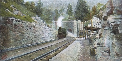 |
| The completed Hoosac Tunnel in operation |
Another practical difficulty was found to exist in the use of two of the columns as steam pipes; the men in moving the stands would frequently grasp the hot pipes instead of the cold ones, and from this cause there was a liability to accident by letting the stands fall. A careful consideration of all the inconveniences found to exist in the use of the four column stand as originally constructed has led to the substitution of keys or wedges instead of screws wherever practicable, and the final result of many improvements is exhibited in the stand with two columns, represented in Figs. 13 and 14. Instead of four set screws at the bottom the base rests on a cast iron tripod 1, in which are three steel points, which, by means of a ball and socket joint, 2, accommodate themselves to the inequalities of the surface, and require no adjustment whatever. The base is hollow, and divided by a transverse partition into two apartments 3, 4, into one of which the live steam is admitted and into the other the exhaust. The connections of the steam and exhaust pipes are shown in Fig. 13. The top of the base is shown in Fig. 16, with the position of the three steam connections and globe valves 5 and the three exhaust connections B, which require no valve. On the base the two columns are placed, and attached by means of a screw cut on the outside of the column, or by rivets, The most convenient mode of attachment is by casting projections on the base, over which the columns can be placed and secured by riveting. The size of the columns should be about 4 in. exterior diameter, the thickness 3/8 in., and the material wrought iron. The connection at the top is by means of a strap, 7, 2in. deep, ¾ in. wide, with rings, 8, to embrace the columns tightly. To obviate the loss of time and the instability which result from too great length of the top screws, a second tube is provided to slide inside the column, like the tube of a telescope (see details, Fig. 12). This tube may be extended 1 ft. or 18 in. at one movement, and held by a pin, 9, which passes through holes in the column, and upon which the bottom of the inner tube rests. The inner tube at its top end carries a nut, 10, to which it is rivetted, and through this nut passes the steel-pointed set screw 11, secured when in place by a jam nut 12, or by passing a rod through the holes in the screws of the two columns, which furnishes a convenient mode of locking them. Each stand may contain three or four drills, but three is a convenient number in driving a tunnel gallery 6 ft. high. The distance between the columns of each stand is l0 in., or 18 in. deep from out to out. The number of stands in use will depend upon the width of the gallery. In a heading 6 ft. high and 15 ft. wide it might be expedient to use four stands mounting twelve drills in order to secure the most rapid progress possible; but two stands with six drills would give very satisfactory results, as two or more sets of holes could be drilled before blasting. Each drill is mounted on a cross bar 12 (see details, Figs 9, 11, 17, 18), attached to the columns by means of clamps 13. These clamps are made in two symmetrical halves, cast from the same pattern. A projection in front carries the bar 12, which is secured by keys on each side of the clamp, Fig. 15. The back part of the clamp is circular in section, and a ring screwed around it holds the parts together securely. (Fig. 11, B). To prevent movement a block or clamp piece of iron or brass, 16, fits in a recess in the clamp, 17, the inner surface of which is curved to fit accurately the surface of the column with which it is in contact. It is pressed tightly against the column by means of a key, 18, driven behind it, and in a direction at right angles to the direction of the clamp piece. The keys arc all wired, 20, and the clamp pieces notched, so that when loose none of them can fall out, or be removed without taking out the wire. The ring which is screwed on to connect the two halves of the clamp has notches on opposite sides through which the key passes, so that the key not only presses the clamp piece firmly against the column, but at the same time holds both it and the ring in place, so that neither can be removed. This description of the clamp which supports the forward end of the drill will also answer for that which supports the rear end, except that the latter must have an eye, 14, through which the brace rods, 15, are passed. These clamps are also cast in two symmetrical halves, but, instead of the ring to hold them together, there is at the rear end a cap containing a hole through which the brace rod passes, and an independent clamping arrangement, similar to that already described, to hold this rod. The cap serves as a swivel, and is prevented from unscrewing by the rod which passes through it. The keys are placed at right angles to the clamp pieces and to the rods, in which position the jarring, pulling, or pushing on the rods will have but little tendency to loosen them. A third form of clamp, represented in Fig. 17, connects the drill cylinder at its forward end with the cross-bar which supports it. A plug is screwed into the cylinder, which passes through a hole in the clamp, and is secured by a key. A recess in the cylindrical part of the clamp also admits a key to fasten it on the cross bar. To hold the drill when at work, especially in commencing a hole, two points of support are necessary; after the drilling tool has penetrated a few inches the hole itself affords firm support. The cross bar, 12, holds the forward end of the drill cylinder, and the brace rods, 15, passing through the eyes of the clamps, hold the rear end. These brace rods are about ten inches long; they are straight and round, three-quarters of an inch in diameter; they are connected with the cylinder by means of an eye, 20, Fig. 10, which passes over a pin, 21, screwed into the end of the cylinder. The eye is prevented from falling off by means of a wire through the end of the pin. The rod is furnished with a universal movement by means of the joint, 22, in connection with the eye, 20. All the parts connected with the support and movement of the drill upon the stand have now been described; it remains to explain the manipulation required to place the drills in position. It will be observed that there is not a single screw connected with any of these movements, that keys have been substituted in every instance, that the keys are placed in a direction at right angles to the direction of the jar or strain, so that there is but little tendency to rattle loose; that every clamp piece has a transverse notch, through which the key passes; and that every key is wired: As the distance between the columns is ten inches, while the width of the drill cylinder is six inches, and its length ten, there is a play of four inches to the right or left, and as the point of rotation at the forward end is about four inches in advance of the line of the columns the rear end of the cylinder, when placed on one side, will swing clear of t he column on the other side. This will admit of a range of horizontal movement exceeding ninety degrees, a degree of mobility never before approached in any previous system of mounting, and impossible with any other than a very short machine. In a vertical direction there is no limit to the movement; the drills may be placed at any angle, from vertical upwards to vertical downwards. As the drill cylinder can be placed in contact with either column it is possible to work as closely to either side of the tunnel as may be necessary. A narrower stand would possess no advantage in this particular. To shift the position of a drill it is not generally necessary to move the forward pivot; it is only required to loosen the two column clamp keys and the two rod clamp keys to secure a movement both horizontal and vertical. Less than a minute should suffice for this adjustment. The india-rubber pipes which carry the live and exhaust steam to and from each drill are not disconnected, except when a drill is to be sent to the shop for repairs; they remain attached to the drills, and stand and do not interfere with the movements. If a drill point should break or become so dull as to require sharpening, the box at the rear end which holds the feed nut is thrown open, the drill rod with the nut attached is drawn out, and another rod and nut inserted; there is no necessity for losing time to back the drill rod out by unscrewing the feed nut as in other drills. If it should become necessary to remove one of the machines from the stand and substitute another, this, too, is very rapidly effected. The key in the plug at the forward end of the cylinder must be knocked out, the wires removed from the pins at the rear end, and the hose disconnected. As the hose couplings are made upon an improved plan without screws, the whole operation is performed with great celerity. All the couplings of pipes and hose are connected by simply pressing them together with the hand and disconnected by pressing a spring and pulling them apart. In ordinary tunneling, the most difficult portion of the labour, and that which consumes the most time, consists in drilling the holes for the blast. At the Hoosac Tunnel, where accurate records of all the operations have been kept by statisticians employed for the purpose, it appears that the average progress in drilling by hand in the talcose slate rock, a rock of average hardness, is 46 in. per day of eight hours, or about 10 min. to an inch. In the same rock the machines should readily drill at least 2 in. per minute. The substitution of machine for hand labour in drilling is therefore very important, if other essential conditions can be also complied with; these are – 1, a mode of erecting, applying power, and removing the drills expeditiously; 2, facilities for resuming drilling operations immediately after a blast, without waiting until the material blown down has been removed on cars, and without interfering with its removal; 3, ample power· for operating the drills; 4, perfect ventilation at all times. Other conditions of accelerated progress, which may be considered secondary, are – 5, a convenient mode of furnishing light; 6, a convenient mode of maintaining the alignment and grade; 7, the best mode of loading and blasting holes; 8, the mast safe and powerful explosive agent; 9, the best mode of protection against stone projected by the blasts.
| Page copyright © 2026 Mark A. Miner |